For the schoolchildren of tomorrow
| Front Page | Welcome | Two | Three | Four | Pentagram | Six | Spirals | The Plot Thickens | Astronomy | 2006 Formations |
I. The Fractal Process
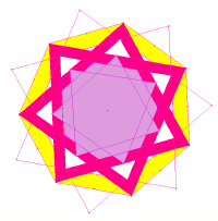
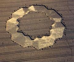
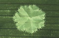 This one's the Everest of crop circle geometry. Only now, nearly ten years later, do I feel competent to analyse it (1). It was huge - about twelve tons of wheat went down over 1.6 acres. It was complex because it was fractal (and there was a lot of debate over this question at the time) , and its heptagon-fractal process had not been envisaged by mathematicians - or, so I here suggest (2). It was based upon a fourteen-fold division of the circle. Its fractal-cascade went though three steps of iteration. Alas, storms damaged the formation on the night after it appeared and so there are few decent pictures of it (3). In the overhead-photo, one can see that each of the seven sectors has seven small circles surrounding it, thus giving 49 in all. This emphasizes the deeply sevenfold nature of the formation.
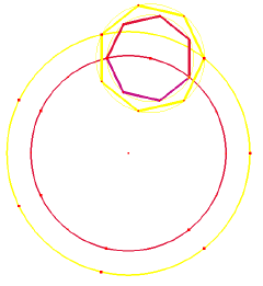
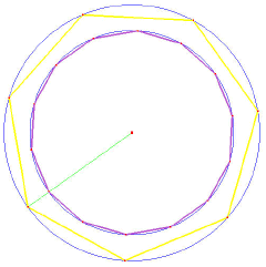
 Place a heptagon onto the circumference of a circle divided into 14, so that it takes up one-seventh of that perimeter, as shown. Notice how it thereby becomes divided into a 3:4 ratio, with 3 of its sectors inside the parent circle. Then put a slightly larger circle around the first one, and a larger heptagon around the second, so that it again cuts into one-seventh of the big circle. Let it expand until these again lock into that 3:4 ratio, but this time the 3 sectors will be outside the large circle. Then these two pairs of circles will then be in the same ratio to each other, i.e. they are self-similar! Mr Dolf Braat pointed out that their radii are in a 4:5 ratio. That is a fractal process, it will keep repeating.
 The two big circles and the larger of the two secondary circles in our diagram were inscribed on the ground, shown in the little diagram (drawn by Bert Janssen (4)).
II Dolf Braat's Vision
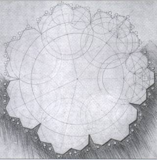
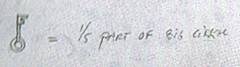
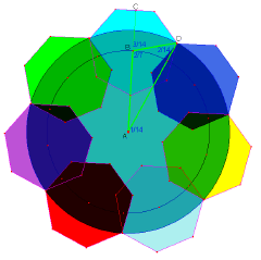
Dolf Braat constructed a master-diagram of this formation (5), and wrote beside it a 'key' saying, '1/5 part of the big circle'. Accordingly, we draw two concentric circles, one a fifth larger than the other (i.e. its radius is 125% of the inner circle). We then divide the inner circle into 14 equal parts, and the outer by 7, making these in alignment. So this formation uses 1/14ths of a circle.
 Then, we construct seven heptagons around this, so that each of these has just three sides outside the outer circle, making them interlinked. The centres of the heptagons stand on the inner circle and each has two corners on the outer circle. We then construct a triangle based on the straight line from the centre A to the mid-point of one of the heptagon sides, C. The angle CBD is 3/14th of a circle, because each side of the heptagon makes 1/7th of a circle angle at the centre. Hence the angle ABD is 4/14ths, or 2/7ths. The centre angle DAB is 1/14th of a circle, therefore the third angle of the triangle, BDA, is 2/14ths, or 1/7th of a circle (just under 52°). Thus the three angles of this key triangle are in the ratio 1, 2 and 4, these adding up to 7. Two of its side-lengths AB and BD are essentially required for construction, while arcs with the radius AD were inscribed on the ground.
 Using the sine rule, we can see that the outer circle radius AD has to be AB x sin(2/7ths)/sin(2/14ths) = 1.247. Thus Dolf Braat was almost right, near enough for any construction purposes; heptagon geometry will always give incommensurate ratios, and any simple ratio will be approximate.
This design might be appropriate for a temple ground-plan. It brings together the numbers 5 and 7.
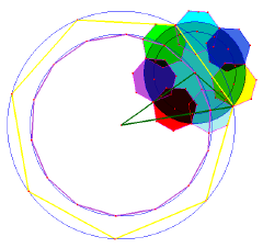
Seven of these structures are then placed onto a larger circle. How does that happen? Just the same ratios are here used, again! In each one-seventh of the big circle, three of the smaller heptagons appear, i.e 3/7ths of each heptagon are 'visible' around the outside, and on each of these, three sides are manifest, so again 3/7ths of each heptagon are visible. So this is an iterative, fractal process.
Here we see just one of the seven heptagons inserted, and again we've drawn in the Key Triangle. The maths is just the same as before. Let the fundamental radius be A (regrettably no-one measured this - it was rather huge), and let the bigger concentric circle radius be A', both visible on the ground-lay. These are in a 5:4 ratio as we saw earlier.
Let's call the radii of the secondary circles b and b' (AB and AD in previous diagram) and c the radius of the little 3rd generation circles (in which heptagons are inscribed - see the Dolf Braat diagram) round the outside. Thus the big circles of radius a and a' and the arcs of radius b' were inscribed on the ground. Then, a'/a = b'/b = 5/4, and a' - a = c! The radii of the 3rd-generation heptagon circles (around the outside) equals the difference between the two primary radii. How did that happen?
If you were constructing this pattern, maybe as part of a mystical park-design, you would need 42 heptagon slabs. That is because each set of seven, forming one-seventh of the whole, shares a heptagon with the neighbouring ring. Each of the seven sets of seven heptagons interlock, by sharing a heptagon in common.
III The Family of Heptagons
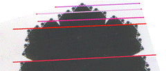 Alternatively we can view this formation more in terms of straight lines, and start by noticing that a set of five parallel lines touches the sides of this formation, for each of its seven directions.
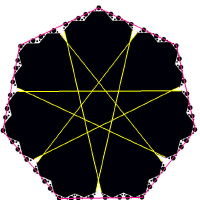
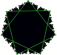 This is I suggest the only shape which embodies all three of the heptagons: the star heptagon, the bi-heptagon and the simple heptagon (6). From the Dolf-Braat diagram, we note that the centres of the 3rd-generation heptagons also lie on a heptagon, with each straight-line side of this heptagon going through four of them (so there are 21 in all). There are alas very few decent pictures of it, partly because of damage by wind and storm the next night, and partly because (reputedly) cameras didn't work when flying overhead. A month later its companion form appeared, the bi-heptagon laid down in Tawsmead Copse (7).
1. For my early attempt, see 'The Heptagon Family' in The Cereologist' Summer 2000.
2. for a fractal heptagon (in hyperbolic space) see: www.thoughts.com/blog/photos/islamicseptagonalhyperbolicpattern-6436/
3. Thanks to Steve Alexander for use of his picture. It was taken the day after the formation appeared and the storm damage is evident. Colin Andrews got his picture on the day, and its much clearer: http://ccdb.cropcircleresearch.com/info.cgi?d=uk1998ch
4. For an early analysis of these two heptagonal formatuons, see Bert Janssen's www.cropcircleconnector.com/Bert/bert98a5.html
5.This was the last thing Mr Braat ever did: he died right after returning to Holland (falling off a balcony) and left this diagram at Francine Blake's crop-circle conference.
6. John Dee used a combination of the three heptagons in his angel-communication board, presently at the Ashmoleum Museum, Oxford: www.heptarchia.net/636/Aemeth.html
Note that the heptagon and bi-heptagon are in the identical relationship in Dee's board, as in the East Field formation.
7 For Norwegian comment on these two see: www.martinkeitel.net/cropcircles/tawsmead98/taw.page5.html and www.axve02.dsl.pipex.com/cropcirc/chap8/www.martinkeitel.net/cropcircles/tawsmead98/taw.page5.html
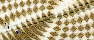
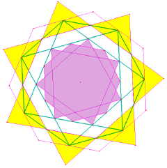 One month after the giant fractal heptagon appeared, and not very far away, there appeared an equally mysterious sevenfold pattern; different in its intention, and yet clearly designed by the same Mind. It was enormous, extending over nine sets of tramlines in the wheat. Seven heptagons had been cleverly woven together, in a way that I suspect no-one had tried to do hitherto. Using a program that makes heptagons (1), its not hard to put the patterns together, to reconstruct the form.
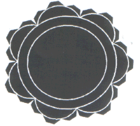
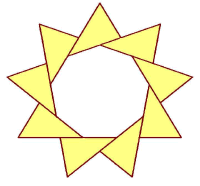
Starting off with a regular heptagon, one places an alternate heptagon (one which goes twice round in its construction) inside it, touching its corners. Then another heptagon is made to touch the centre of its sides, i.e. it has suffered a 1/14th rotation (and a contraction of cos (/7), about 10%). Note that the sides of the bi-heptagon are here twice the length of those of the heptagon. Thereby we construct the inside pattern of this formation, using three heptagons. Its 28 equal-length sides each had three little circles along its inside, making 84 in all (12 x 7), so multiples of seven echo in this construction.
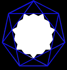
 Marker lines were laid down in the flattened wheat, which made an interlinked heptagon plus alternate heptagon (here coloured green, and thicker than the other lines). The corners of these coincide, so the laid-down geometry was sevenfold, whereas that of both the inside and outside patterns was 14-fold. This interlinked pattern held the space between the inner and outer geometry. How remarkable, that one space of flattened wheat was able to define six or seven concentric heptagons. The outer silhouette had 84 little circles around it. One could say that the number 14 was here being emphasised, as there were in all 12 x 14 of the little circles. See if you can spot the 49 rhombi (diamonds) in the overall pattern. The silhouette here shown was done by Bert Yanssen (2).
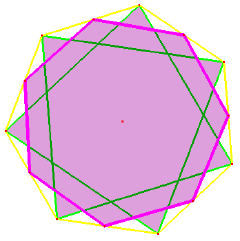
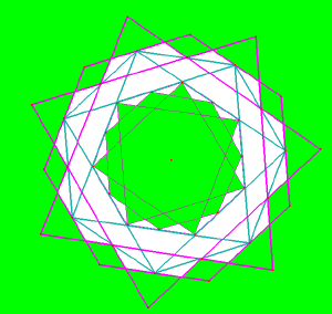
Three or four heptagons plus three alternate heptagons were marvellously interlinked. The outermost alternate heptagon has its points of intersection lying on the heptagon-on-the-ground (i.e., inscribed in the wheat). The heptagons inscribed on the ground were the key for its decipherment: one should hesitate before describing them as 'construction lines' because, as Figure 3 shows, various other lines also traversed the space. We can draw in a thick 'alternate heptagon,' latent in the pattern. This structure would be suitable for a temple-window. More lines of symmetry inter-relate the inner and outer designs, noticed by Martin Keitel (2). They enable another bi-heptagon to be drawn in, rotated at a 1/14th angle to the previous one.
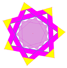
 Nearly ten years after its formation, the correct structure of this grand and enigmatic masterpiece is here given, for the first time! But still, the questions hover: what was the Mind which conceived these haunting 14-fold geometries, of such complexity, and what was the Thought which led to the transition from one to the other, over one month? It's maths, but not as we know it: as if some master-geometer were attuned to Mathematics, Mysticism and Architecture.
1. I used the CABRI geometry package.
2. www.cropcircleconnector.com/Bert/bert98a.html
3. www.martinkeitel.net/cropcircles/tawsmead98/taw.page5.html
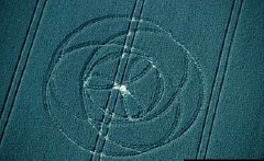
 People like wearing a pendant of this well-integrated design www.lucypringle.co.uk/merchandise/necklace.shtml - and no wonder, for it brings together 3, 6, 9 and 12-fold symmetries. An equilateral triangle, rotated through two steps about its centre, gives a three-triangle pattern.
 This subtly metamorphoses as it were into nine triangles shown. Each have angles of 60° and 40°, i.e. they are not right-angled). But also, the design within subtly echoes the number nine. How does it manage that?
There are six whirling moons at its centre. No-one could account for these, until Bert Janssen's book of 2004. The Circlemakers, it turned out, had used the same Torus design of two years earlier (section 2) - twelve circles standing on a circle half their radius www.lucypringle.co.uk/photos/1997/uk1997bf.shtml#pic2 - and merely shaded in every alternate crescent. What one may find unnerving here, is the sheer extent to which all of the construction lines have faded away; they were quite absent from the ground. Only six 'whirling moons' remain, of the earlier pattern. Its central circle is one-third the radius of the outer circumference, so that 9 is the ratio of their areas. Thus inner and outer reflect each other, and six- and nine- fold designs are here integrated.
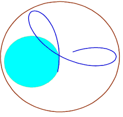
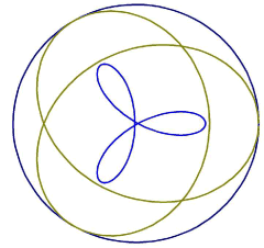 A cycloid is the curve traced out by a point on the edge of a wheel as it rolls along. This diagram shows one being traced out, by a wheel moving inside another one twice its size. This shape is called a 'trefoil' and its equation is r = sin3
![]() . One can express this as a fourth-power equation. In both of these formations the radius of curvature is continually changing, ropes wouldn't make them. The outer curve is rather different and, for the two curves to touch, its equation has to be 4r = 5 + sin{1.5(
. One can express this as a fourth-power equation. In both of these formations the radius of curvature is continually changing, ropes wouldn't make them. The outer curve is rather different and, for the two curves to touch, its equation has to be 4r = 5 + sin{1.5(![]() -90°)}.
-90°)}.
The two touch when ![]() = 90°. What are its other two values where they touch?
= 90°. What are its other two values where they touch?
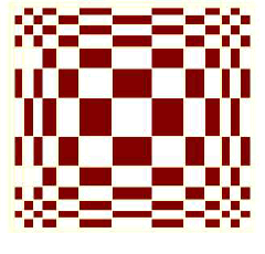
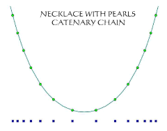 Try the catenary' Guy Atkinson said to me, over a lunch in Guildford. I had just spent two weeks trying to fathom this projection, in vain. No ratio or arithmetic sequence would give it, nor would any projection using a semicircle, an ellipse, parabola or hyperbola. The catenary is the curve made by a chain hanging under its own weight. It has a flatter bottom than other curves: I found that its projection, and no other, gave the large central square: others eg a parabola gave a too-small central square. The catenary is made with 'hyperbolic' functions: cosh x makes the curve and sinh x gives the equally-spaced points upon it (1).
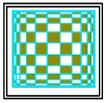 This formation was described by cerealogist Michael Glickman as 'the most assured expression of graphic three-dimensionality' which the Circlemakers had yet given us. From its centre there was sequence of seven squares to the edge, then there was a half-width 'edge' around the perimeter, which helped to give its marvellous 3-D 'rollover' effect.
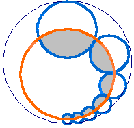 Twelve touching circles stand on a ring. They increase in size gradually over six steps, with the last six times bigger than the first. You or I might make them increase by a fixed proportion (A) but that
 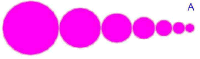 isn't how the Circlemakers did it: their method (B) gives a more organic feel to the process, with the ratio between adjacent circles itself increasing at each step.
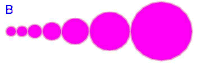 We might call this, accelerated ratio. Thus the first step, from the first to their second circle, showed a mere 9% increase, while their last step amounted to a nearly 70% increase. With their centres all on a circle, this allowed them just to touch (approximately) an unseen, enveloping circle. Then this whole pattern was shrunk and reflected, and neatly fitted inside.
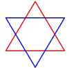
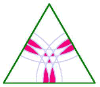
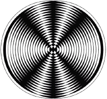
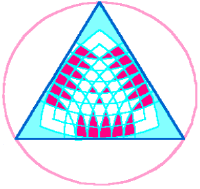 Seeking for unusual harmonies, the Circlemakers divided each of three sides of a Star-of-David triangle by 14. Using this, they sat up a three-way interference pattern. Mathematically, the aim of this exercise was presumably to ascertain how well the three 8th arcs (4/7th of the whole) passed through the centre, which they do quite well. There is a strong focus upon this centre-point with three mini-triangles around it. Thus, 4/7 = 1/
![]() 3 to within 1%. Why anyone would want to show this, in an English wheatfield, is another matter (Also, the 4th and 12th arcs just touched the Star-of-David sides). Around the outside were three sets of 'spokes' 5, 5 and 4, adding up to 14 as an indication of this as the number on which the design was based.
3 to within 1%. Why anyone would want to show this, in an English wheatfield, is another matter (Also, the 4th and 12th arcs just touched the Star-of-David sides). Around the outside were three sets of 'spokes' 5, 5 and 4, adding up to 14 as an indication of this as the number on which the design was based.
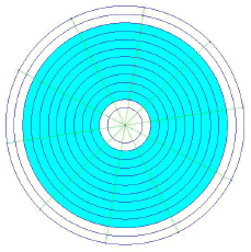
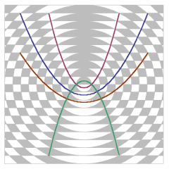 In 2005, a hitherto unheard-of manner of constructing a parabola was demonstrated, in an English cornfield. A whole nest of parabolae were laid down. Remarkably, these parabolae all had the same focus, i.e. they were confocal. Here's a picture: a parabolic mirror focusses sunlight onto a single spot, and so confocal parabolae would all focus it onto the same spot - they would all have the same focus. That focus is at the very centre of this diagram.
 The pattern was generated by nothing more than a set of concentric circles, with equal increment of radius, and parallel straight lines intersecting them. The equations of the parabolae shown are x2=±2ay+a2 where 'a' has values 1, 3, 5 ..., if the circles have radii 1,2,3 etc. NB, we can write the equation of a parabola as x2=2ay, and its focus will then have the co-ordinates (0,a/2); then, shifting that focus to the centre, will give the above set of equations.
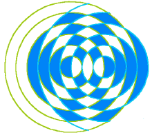
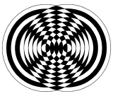
 Try striking a tuning fork, and then slowly rotate it; you will then hear the sound coming from it grow alternately louder and dimmer. This shows interference taking place, between the two different sources of sound. The crop-circle diagram shows this. If the two sources are separated by one and a half times the wavelength of the sound, then the lines of constructive and destructive interference will be as shown in this 2005 formation: showing where the sound grows louder and softer. The dark lines in the diagram are zones of silence. It is made from two sets of twenty concentric circles.
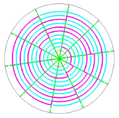
 In a pattern which appeared a year earlier, the two sources were positioned further apart, at two and a half wavelengths. This created five interference lines (i.e., where the sound fades away) instead of three.
Thanks to Allan Brown for use of his diagrams in 'Crooked Soley' 'nest of parabolae' and 'sound wave interference' ; and to Pete Howard for his comments on the parabolae of 2005.
 Four days after this formation had appeared, Mike Reed, a retired astrophysicist from Arizona university, realised that it encoded the first ten figures of
 ![]() . He saw that its last figure had been 'rounded up,' 3.141592654 - to 12 figures it would be 3.14159265358. He e-mailed Linda Moulton Howe who contacted Lucy Pringle in England. It soon made newspaper headlines around the world.
. He saw that its last figure had been 'rounded up,' 3.141592654 - to 12 figures it would be 3.14159265358. He e-mailed Linda Moulton Howe who contacted Lucy Pringle in England. It soon made newspaper headlines around the world.
A circle is divided into ten sectors, plus there are ten rings around that centre, so that the 'ratchet' design of this formation gets written onto these ten rings. The tenfold division of the circle here signifies use of a decimal number system, and then the rings contain the ten figures of ![]() here given. In the succinct words of Mike Reed, the radial jumps are the indicator of each segment.
here given. In the succinct words of Mike Reed, the radial jumps are the indicator of each segment.
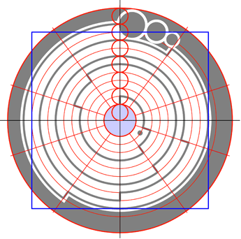
 From the outermost circle there is a 14-fold division of circle radius (as Bert Janssen pointed out) and the ten circles are inscribed within these, in a manner that makes the larger circle just four times bigger than the smaller. The centre circle of flattened barley has a radius of two units, followed by the number '3' which is written on the 3-unit circle, then the last number 4 is written on the 12-unit circle. The cryptic pattern revolves exactly four times around, and it does that because these ten digits of
 ![]() add up to 40! The Circlemakers always want whole-number ratios, so its wonderful to see how they have tackled the unending, transcendental number pi. The three bubbles at the end indicate that the numbers of
add up to 40! The Circlemakers always want whole-number ratios, so its wonderful to see how they have tackled the unending, transcendental number pi. The three bubbles at the end indicate that the numbers of ![]() just continue forever. The decimal point after the first number 3 - that is, three tenths of a circle at the inmost part of this design, was the clue whereby Mike Reed recognised the number
just continue forever. The decimal point after the first number 3 - that is, three tenths of a circle at the inmost part of this design, was the clue whereby Mike Reed recognised the number ![]() .
.
![]() is about squaring the circle. Bert was intrigued by a straight-line footpath touching the outer-but-one ring. Does our path through life involve squaring the circle, which would traditionally have something to do with perfection? This path indicated where a square had to be drawn, he felt, that would 'square' the outermost circle i.e. have the same length. A square constructed on that ring will indeed 'square the circle' for the outermost ring to 0.04% accuracy. (Hint: the square has side half-length 11 units, the outer enveloping circle has radius 14 units.) Oddly enough, multiplying together these first ten numbers of
is about squaring the circle. Bert was intrigued by a straight-line footpath touching the outer-but-one ring. Does our path through life involve squaring the circle, which would traditionally have something to do with perfection? This path indicated where a square had to be drawn, he felt, that would 'square' the outermost circle i.e. have the same length. A square constructed on that ring will indeed 'square the circle' for the outermost ring to 0.04% accuracy. (Hint: the square has side half-length 11 units, the outer enveloping circle has radius 14 units.) Oddly enough, multiplying together these first ten numbers of ![]() gives 360 x 360.
gives 360 x 360.
Thanks to Bert Janssen for use of image.
The catenary is given by y = cosh(x/a) or y = a/2(ex/a + e-x/a) where 'a' was equal to 0.83. The distance along this curve is given by sinh(x/a).
Thanks to Frank Laumen for use of his Tri-Cycloids photo and to Bert Janssen for his heptagon diagrams.
'A crop circle thought to be inspired by a formula acclaimed as the most beautiful in all mathematics has appeared on a hillside in Wiltshire,' reported The Telegraph, on the 24th. It quoted Lucy Pringle as saying, 'This is one of the most profound and complicated equations of the past 2,000 years, and we think the crop circle is some form of visual translation.' In computer ASCII code, each character is 8 bits, and a 'bit' is dual, it's plus or minus, one or zero. There are said to be 8 bits in one 'byte'. The design which appeared was twelvefold, it was a twelvefold division of a circle. Each 'spoke' had two sets of the eightfold code on either side, one being a mirror-image of the other. The code was binary, in that a line either was present, or was not present. It was a system of 12 'bytes' . or 24 octets, each one duplicated. | 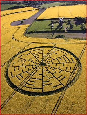
|
If we express them as binary codes, they all started with a zero:
01110000 * 01101001 * 00101001 * 00110001 * 00111101 * 00110000
Mr'Grailseeker' decoded it the very next day! On 23rd May, he decided that the code should be read starting from the 'spoke' that was pointing towards a nearby windmill, he felt that was its beginning. Working clockwise around the circle and out from the centre, this gave him
'It referenced both the turning wheel of the windmill and the twelve-part division of the zodiacal cycle, the cosmic wheel,' he commented. But, what did it mean? The presumption is, that they were trying to express 'Euler's formula' the most famous formula in mathematics, of
The ASCII code will not give Greek letters, no '![]() ' symbol was available. So, '
' symbol was available. So, '![]() ' had to be written 'pi,' which means that the formula required twelve symbols. The ASCI symbol ^ means 'to the power of,' thus 4^2 would be four squared, 42 = 16.
' had to be written 'pi,' which means that the formula required twelve symbols. The ASCI symbol ^ means 'to the power of,' thus 4^2 would be four squared, 42 = 16.
The 'natural logarithm' constant 'e,' raised to the power of ![]() times the square root of minus one, plus one equals zero. That was published by the brilliant blind Swiss mathematician Leonardt Euler - maybe the greatest mathematician who ever lived - in 1748. For mathematicians his formula is a bit like a proof for the existence of God.
times the square root of minus one, plus one equals zero. That was published by the brilliant blind Swiss mathematician Leonardt Euler - maybe the greatest mathematician who ever lived - in 1748. For mathematicians his formula is a bit like a proof for the existence of God.
So, had the formula gone wrong? Did the Circlemakers make a mistake? We'll here ignore a large volume of web-comment, and just quote 'Grailseeker' again:
'I think that the more likely scenario is that the circle-makers made a genuine mistake. The binary encoding for 'h' - 01101000 is just one binary digit different to that for '(' - 00101000. The extra opening bracket would pair up with the otherwise unpaired closing bracket in the message to give us'
That, I suggest, is as good a story as we are likely to get.
|
Sponsored by Paul Vigay |